About TTH
Aluminum Pergola Manufacturing | Inside TTH
Workshop photographs become useful when they explain what is being prepared and why it matters to the finished installation. Follow the relationship between drawings, component preparation, assembly and packing.
Discuss your project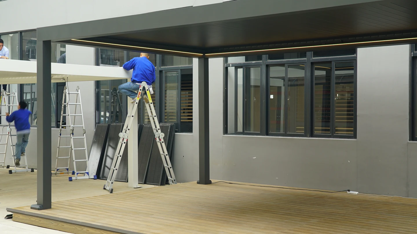
The drawing gives every component a purpose
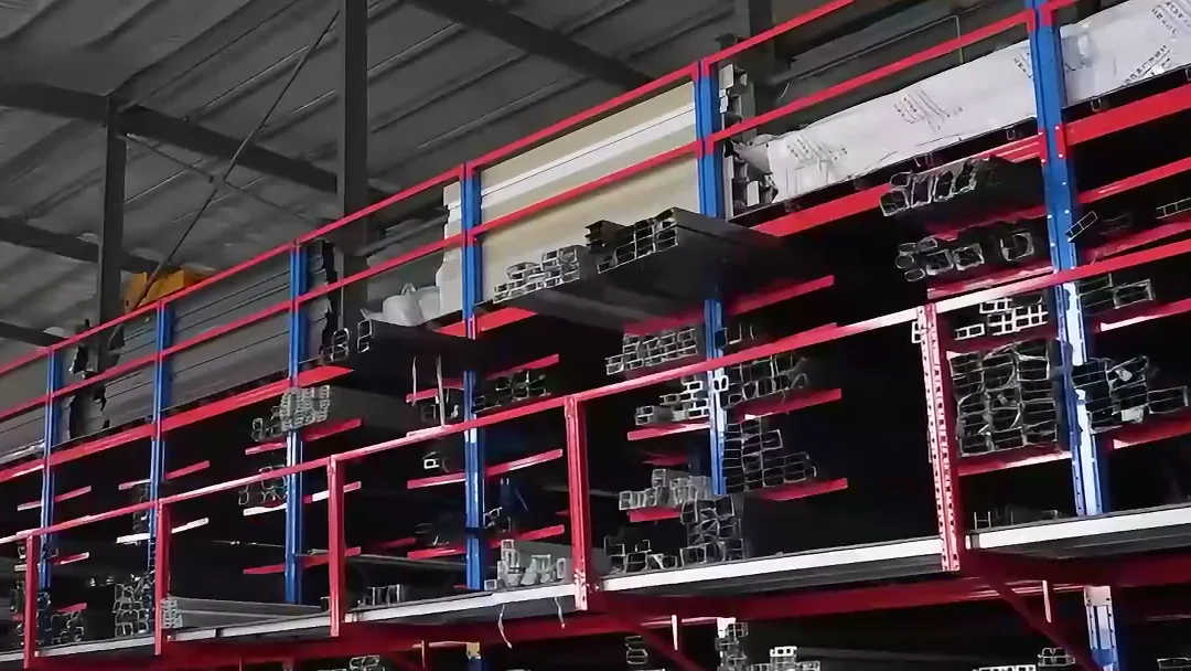
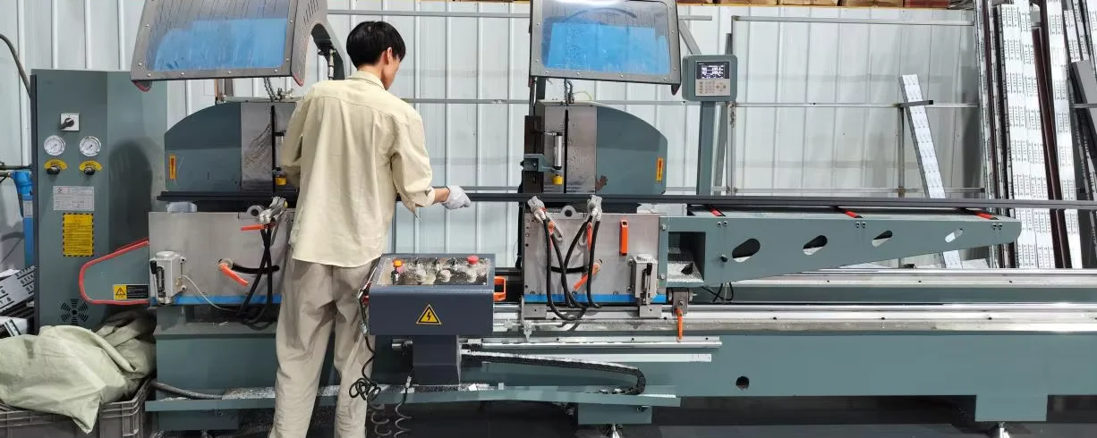
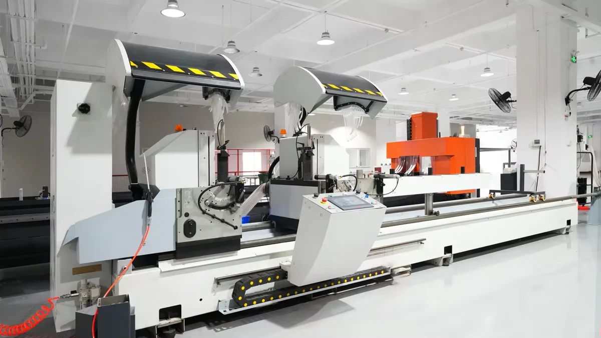
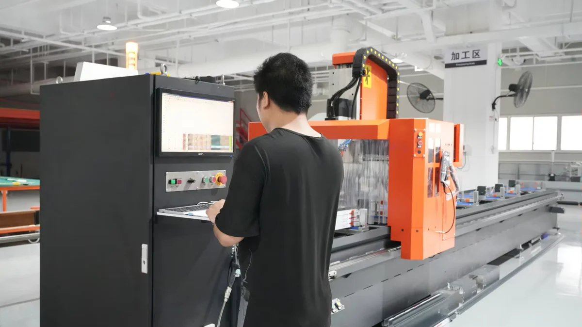
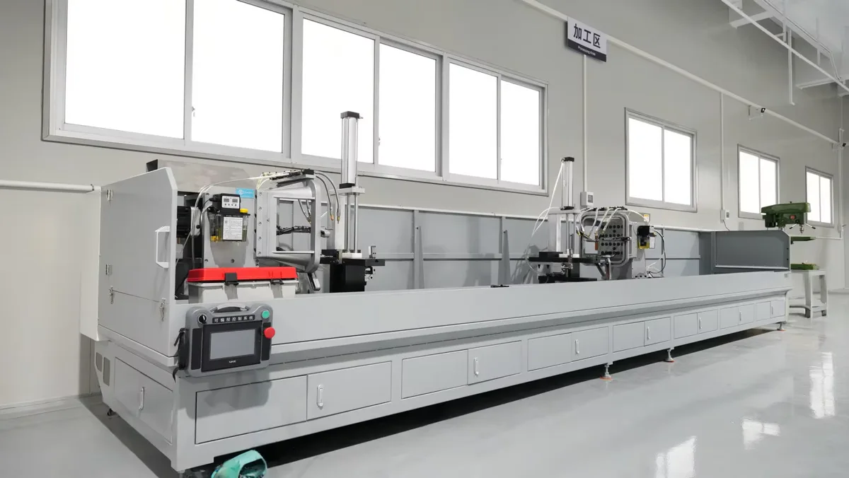
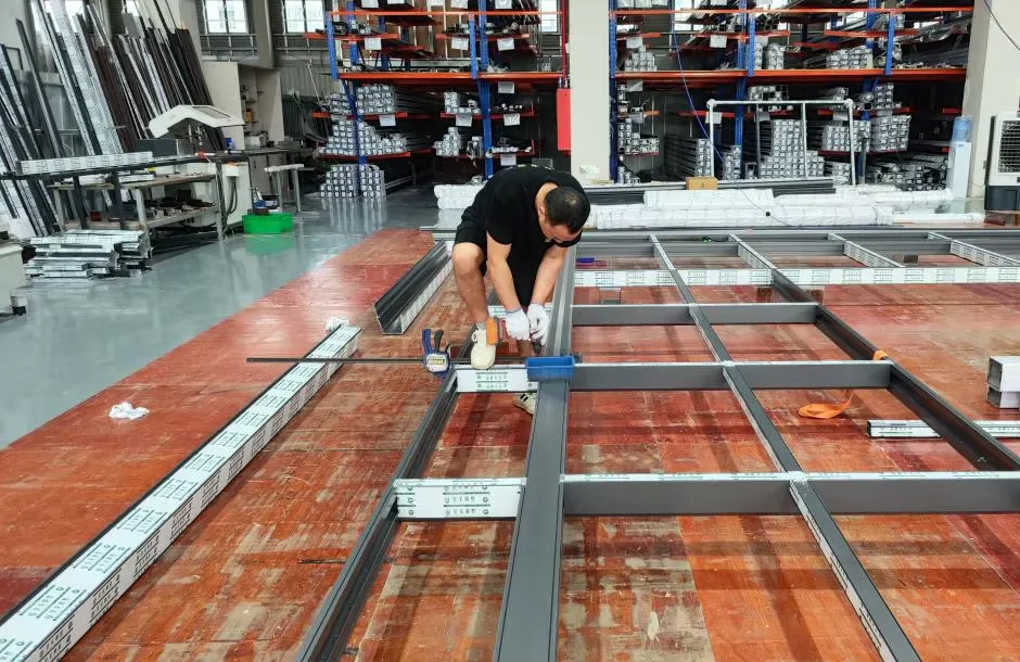
The workshop collection shows profile storage, cutting equipment, a machining station and frame assembly. Each stage answers a different question: which section is required, where a prepared length belongs, and how its connections meet adjacent parts. Before manufacturing, the approved layout should identify support positions, roof orientation, drainage outlets and accessory interfaces. A motor cable route or a screen connection can affect preparation even when it is barely visible in a finished photograph. Resolving these details on the drawing reduces the need to improvise at the installation site.
Different roofs need different review points
For the 145/175 and 200/220 louvered families, review the specified profile set, roof mechanism and planned water route together. A hardtop pavilion needs the roof covering, perimeter details and support layout to agree. Solar-canopy preparation also involves the selected panel arrangement and the interfaces reserved for electrical equipment. For a retractable awning, the fabric, arm arrangement, cassette and mounting details form a separate assembly. Identify the relevant checks for the actual order; a successful showroom demonstration is useful to understand operation, while the supplied configuration still needs its own agreed review.
Make the requested checks visible
Agree the inspection scope while confirming the order. Useful checkpoints include the drawing revision, component identification, accessible dimensions, visible finish condition and the operation of the supplied moving parts. Decide which photographs or records are needed and when the buyer reviews them. A clear packing reference connects a checked component to the package that arrives on site. Where a technical report is requested, match its product, configuration and test scope to the proposal. This creates a more useful handover than a general statement that everything has been checked.
Repeat bays with one changed detail
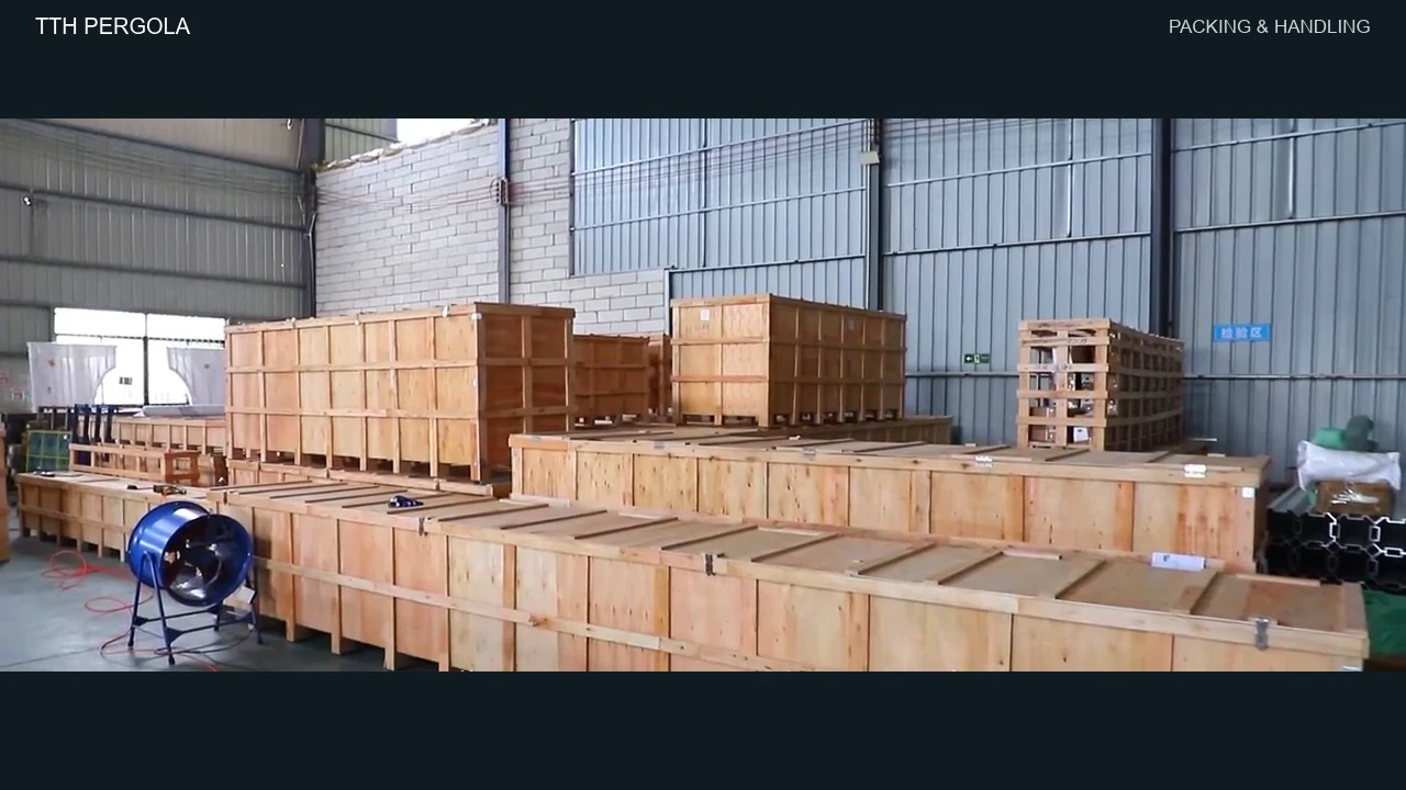
For several matching terrace bays, identify any bay that needs a different drainage outlet position. The overall appearance may be identical, but the affected post and its drawing reference must stay identifiable through preparation and packing. Give the bays clear positions on the layout, connect those positions to component and package references, and show the receiving team which package opens first. Before dispatch, review the packing list against the approved configuration and the unloading plan. Clear component identification connects each supplied part to its intended installation position.
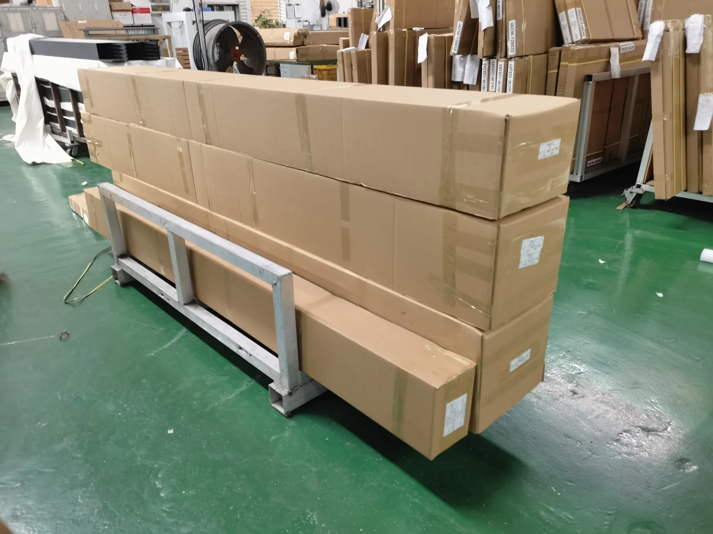
Workshop footage and packing references
BEHIND THE FRAME
See how the details come together.
Look closer at the materials, machining and assembly behind an outdoor aluminum system. From a digital drawing to the workshop, every stage has a different job.
- 01
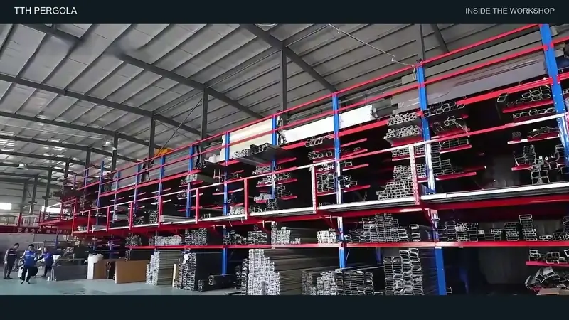
Prepare
Profile stock and cutting equipment.
- 02
Assemble
Frame components brought together on the workbench.
- 03
Demonstrate
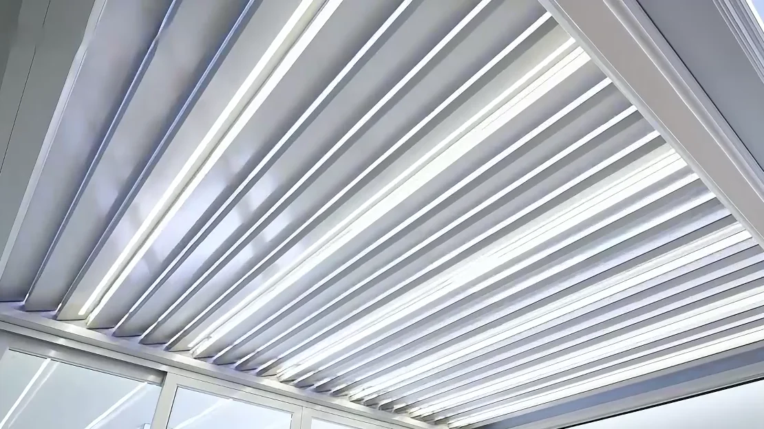
Roof, enclosure and control details in the showroom.
01 / MATERIALS & CUTTING
From profile stock to prepared lengths.
See the stored sections, an operator at the cutting station and the equipment used to prepare profile lengths.
02 / MACHINING & ASSEMBLY
A closer view of the workbench.
Control settings, profile processing and frame assembly each address a different part of the build.
03 / SCREEN & ROOF DETAILS
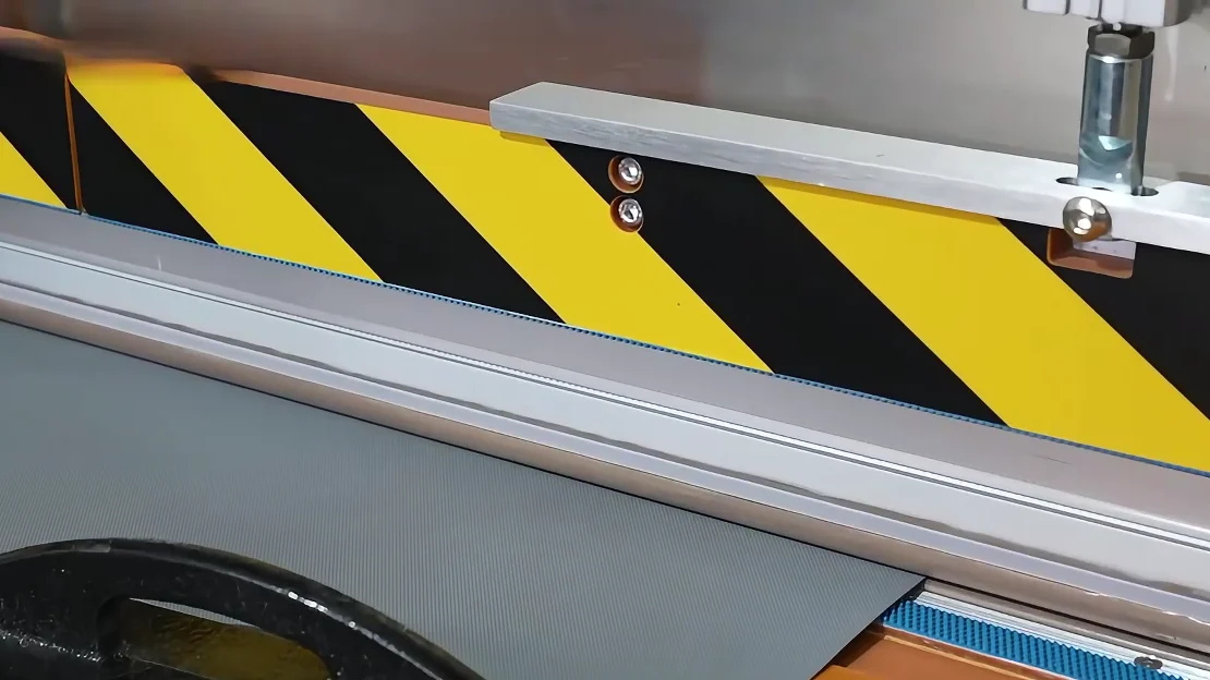
From a component to a working display.
Screen-fabric preparation and a showroom roof give two different views of the system’s details.
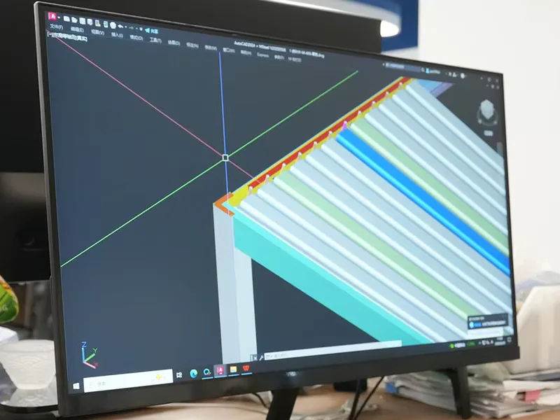
FROM DRAWING TO WORKSHOP
Start with the layout. Resolve the connections.
Drawings bring roof layout, support positions and interfaces into one conversation. Review the proposed dimensions, finishes, drainage route and fixing details before the project package is approved.
Explore technical documentation →