Why TTH
Design & installation documentation
Engineering coordination begins at the interfaces: roof to frame, frame to ground, water to the site drain and equipment to the power supply. Resolve these relationships on the selected configuration before installation starts.
Discuss your project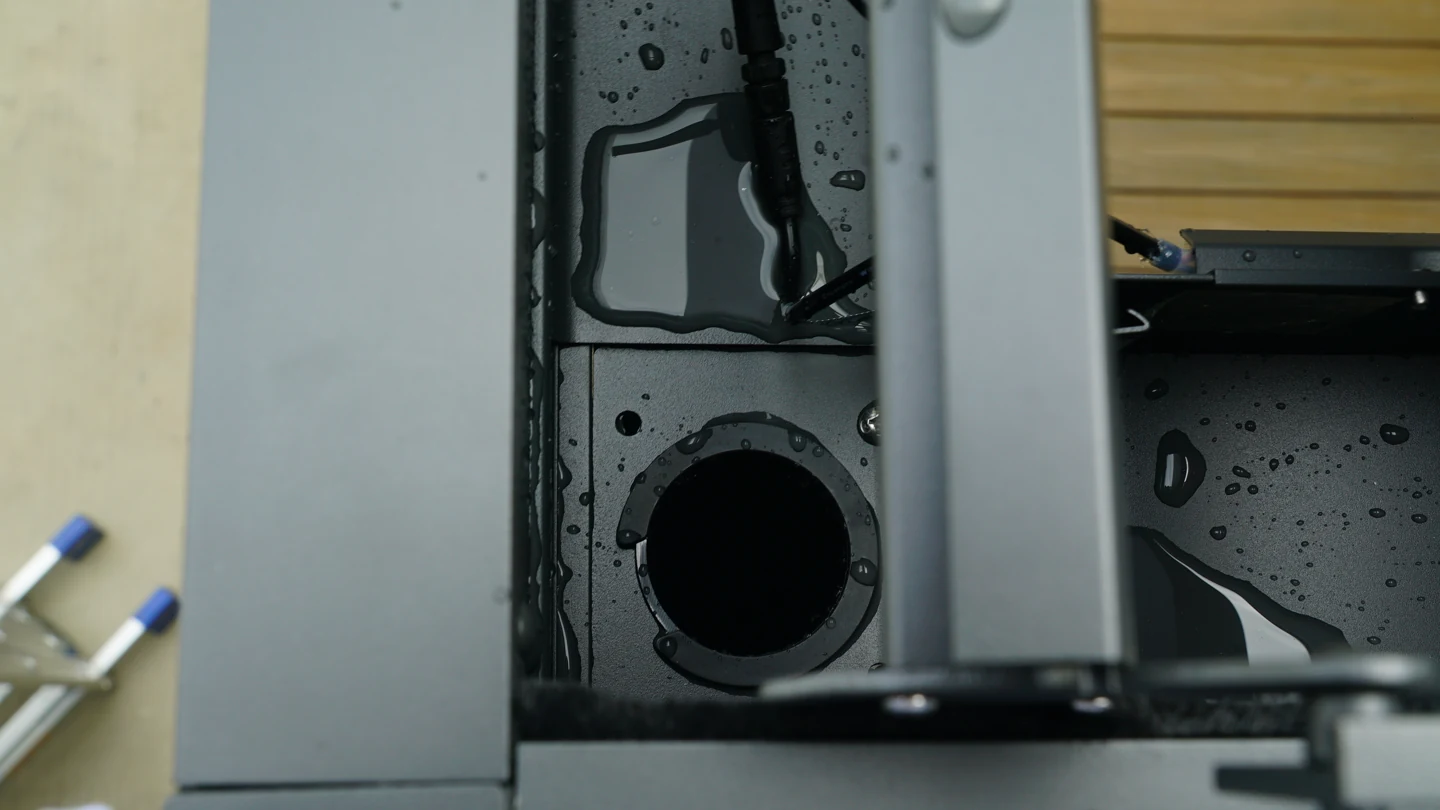
Coordinate layout, structure and services
Start with a plan showing the roof perimeter, posts, openings and nearby building features. Add the support conditions: a terrace finish does not identify the slab or structure beneath it, and a wall surface does not establish a suitable attachment. Then overlay water outlets, power entry and accessory positions. A screen track, downpipe or control cover can compete for the same space. Product profile drawings help identify the supplied system; the actual spans, foundations and connections need review against the site and the locally applicable design requirements.
Read the drainage detail as a complete route
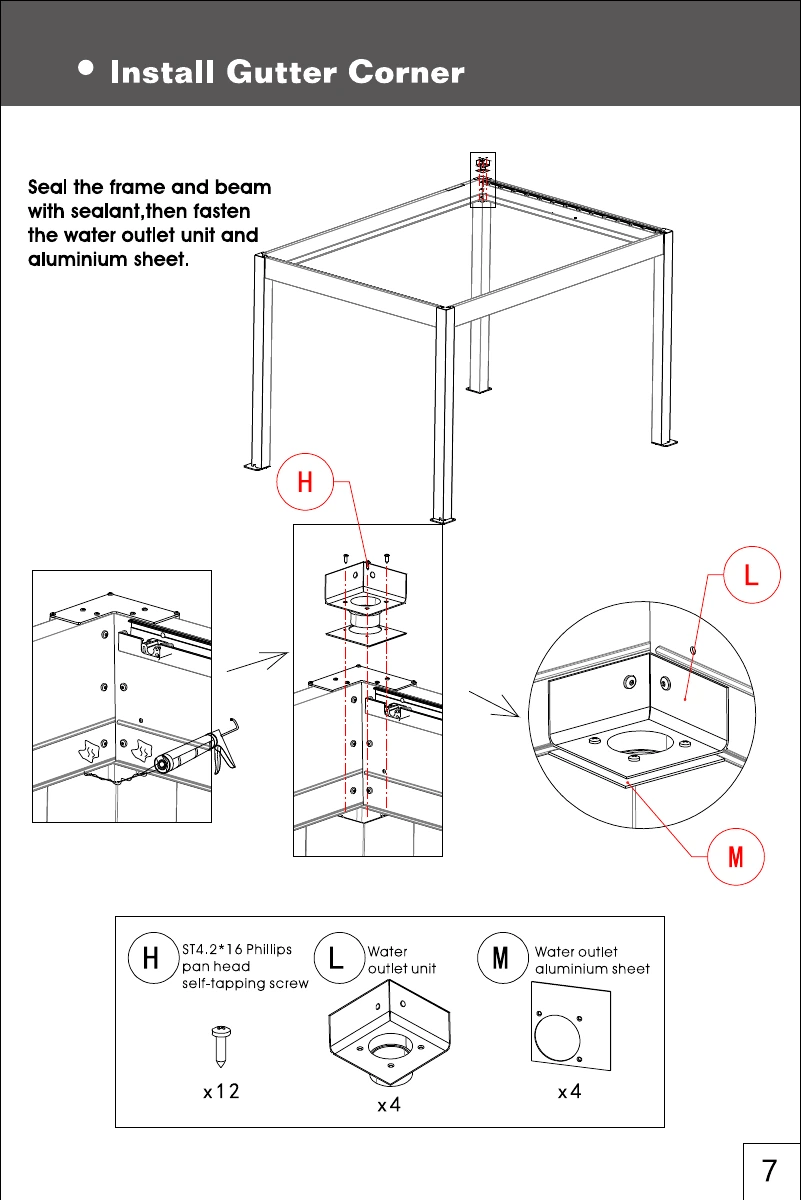
The available 6 × 4 m louvered-pergola manual shows separate gutter corners, water-outlet components, gutter clamps and sealing locations. This matters because water control depends on several assembled interfaces, not only on the roof blades. For your drawing, trace collection at the roof, transfer at the gutter corners, the chosen post outlets and the final discharge point. A planter, raised paving edge or door threshold can change that last step. These manual details explain component relationships; they do not establish a rainfall capacity or confirm a building connection for another configuration.
A practical review sequence before installation
Use the approved project drawing and the matching manual revision together. The manual also separates motor and LED connections and shows covered cable routes, so electrical access should be resolved before those areas are closed. Coordinate this work with the qualified people responsible for the site.
- Verify the measured site, roof orientation, support locations and unobstructed moving-part clearances.
- Confirm structural and electrical responsibilities, access requirements and any unresolved design details.
- Match delivered components to the packing list and record identification before assembly.
- Agree functional, drainage and handover checks for the installed configuration, using its documented procedure.
Different roof systems need different technical packages
A retractable awning needs its own mounting and operating information. A solar canopy needs coordination between structure, modules, electrical equipment and the intended energy connection. A fixed-roof pavilion has different roof details from a louvered pergola. Do not transfer fixing sizes, operating limits or drainage assumptions between them. For a technical review, provide the selected family, proposed size, location, support photographs and available site drawings. Identify which local professional will review the installation so that open questions reach the right person before an order is finalized.